

14-02-2015, 23:15
New forum user and builder

Posts: 870
Threads: 31
Joined: Jul 2014
Weather Station: Conder Weather, Canberra
Country:
Threads: 31
Joined: Jul 2014
Weather Station: Conder Weather, Canberra
Country:

Posts: 318
Threads: 9
Joined: Jan 2015
Weather Station: Darra Weather
Country:
Threads: 9
Joined: Jan 2015
Weather Station: Darra Weather
Country:
15-02-2015, 02:50
Ok my Rx unit has been sitting on a table for the last couple hours on a table to test things out. I fine tuned the offset values for temperature and atmospheric pressures in the code and readings are consistent. Atmospheric pressure is within a couple of points to my local station, and pressure changes correspond in the same direction during my test time.
Cumulus is even talking to it and set the Real Time Clock for me.
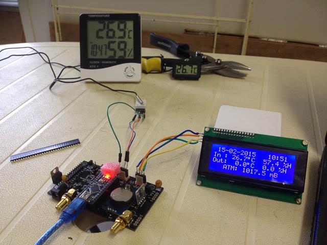
Confession time: My setback I mentioned earlier is that I accidentally shorted my crude temporary temperature sensor leads. Unfortunately my other Nano board let smoke out and did not survive. So pleased I decided to install sockets for the Nano. Now the Nano intended for the TX board is running the RX, and I have ordered replacements. Probably take a week judging by my original order.
Then on the second Nano, the display booted to the welcome screen and then blank, I worried I had done more damage. Especially when I tested the 5v pins with my multimeter and found them running at 3.4 - 4 volts. Evidently that does not seem to worry anything as all is running well since I altered the display refresh line for testing as Werk advised. Thanks again!
Over all this is great!
Cumulus is even talking to it and set the Real Time Clock for me.
Confession time: My setback I mentioned earlier is that I accidentally shorted my crude temporary temperature sensor leads. Unfortunately my other Nano board let smoke out and did not survive. So pleased I decided to install sockets for the Nano. Now the Nano intended for the TX board is running the RX, and I have ordered replacements. Probably take a week judging by my original order.
Then on the second Nano, the display booted to the welcome screen and then blank, I worried I had done more damage. Especially when I tested the 5v pins with my multimeter and found them running at 3.4 - 4 volts. Evidently that does not seem to worry anything as all is running well since I altered the display refresh line for testing as Werk advised. Thanks again!
Over all this is great!
Posts: 870
Threads: 31
Joined: Jul 2014
Weather Station: Conder Weather, Canberra
Country:
Threads: 31
Joined: Jul 2014
Weather Station: Conder Weather, Canberra
Country:
15-02-2015, 03:03
(15-02-2015, 02:50)qldbureau Wrote: Confession time: My setback I mentioned earlier is that I accidentally shorted my crude temporary temperature sensor leads. Unfortunately my other Nano board let smoke out and did not survive. So pleased I decided to install sockets for the Nano. Now the Nano intended for the TX board is running the RX, and I have ordered replacements. Probably take a week judging by my original order.
Did you really see smoke? Or is this smoke and mirrors

My confessions

I have two Nano's out of the three in a damaged state. Both are still in service and will stay that way until the day it completely dies.
Both have a blown fuse that powers the Nano from the 5v's on the USB interface. The fuse is miniature and I can't even see it lol. Both are now powered by the 5Vdc pin.
Both have blown ports. I've had to change the code to change the assigned pins to another working port(s). Changing the Nano is a lot easier than remembering to change the code each upload.
Having a socket does make life a lot easier, wish I still did (I did on the prototype on stripboard).
The Nano's costing only $3 ea is a godsend if you're a tinkerer
Posts: 318
Threads: 9
Joined: Jan 2015
Weather Station: Darra Weather
Country:
Threads: 9
Joined: Jan 2015
Weather Station: Darra Weather
Country:
15-02-2015, 03:27
(15-02-2015, 03:03)uncle_bob Wrote: Did you really see smoke? Or is this smoke and mirrors
My confessions
I have two Nano's out of the three in a damaged state. Both are still in service and will stay that way until the day it completely dies.
Well maybe I did not see it, but I certainly smelt it. That sickly burnt electronics smell that makes your heart sink and stomach churn
 It was directly over the Nano around its LED's, and was noticeably hot. The USB port it was plugged into threw a Windows 7 message that the device plugged in has caused a power surge, or exceeded the port's supply ability and has been disabled. Thankfully the port came back after a reboot. However the Nano never responded even in another USB port, and does not light even in a dedicated USB power supply. As you say, just as well they are not expensive!
  I even ordered another DHT22 sensor just incase, but as you can see in the picture it seemed to escape harm.
The sockets are definitely worth it, and so easy to make.

Posts: 5.415
Threads: 336
Joined: Apr 2014
Weather Station: WeatherDuino 4Pro
Country:
Threads: 336
Joined: Apr 2014
Weather Station: WeatherDuino 4Pro
Country:
01-03-2015, 05:05
(15-02-2015, 02:50)qldbureau Wrote: ... and I have ordered replacements. Probably take a week judging by my original order.
If you ordered from China, due to Chinese New Year Holiday, maybe it will take a little more.
Posts: 318
Threads: 9
Joined: Jan 2015
Weather Station: Darra Weather
Country:
Threads: 9
Joined: Jan 2015
Weather Station: Darra Weather
Country:
01-03-2015, 06:32
(01-03-2015, 05:05)Werk_AG Wrote: If you ordered from China, due to Chinese New Year Holiday, maybe it will take a little more.
Yes it definitely is taking a little while longer this time. I'm hoping they will arrive this week. The transmitter board is all built, and the addition of the ground wire to the transmitter module went really well.
Posts: 318
Threads: 9
Joined: Jan 2015
Weather Station: Darra Weather
Country:
Threads: 9
Joined: Jan 2015
Weather Station: Darra Weather
Country:
07-03-2015, 23:51
My replacement Nano boards certainly did arrive last week. Happy to say Tx code uploaded and board inserted into Tx board sockets. I commented out rain, wind and solar data as I do not have sensors for those yet. Pleasingly I am transmitting outside temp & humidity with no issues, and that is with the boards at opposite ends of the house too!
It's the smaller things I am having a little trouble with. The led on the Rx board will not blink. Even testing the pins with my multimeter I am not getting any voltage pulses. I used header pins for that one so was easy to swap leads around.
On the Tx board again the tx led is not blinking, and I am not getting pulses past T1 - so not sure if T1 is damaged.
I am going to use a radiation shield fan, for which to test I made the high temp 23 degrees. With temp reading at 28 I am just not getting voltage on the fan pins or at the led. If I measure voltage across diode 1 I am getting 9v.
So a little ironing out to do here, but not where I was expecting! Overall I'm going well.
It's the smaller things I am having a little trouble with. The led on the Rx board will not blink. Even testing the pins with my multimeter I am not getting any voltage pulses. I used header pins for that one so was easy to swap leads around.
On the Tx board again the tx led is not blinking, and I am not getting pulses past T1 - so not sure if T1 is damaged.
I am going to use a radiation shield fan, for which to test I made the high temp 23 degrees. With temp reading at 28 I am just not getting voltage on the fan pins or at the led. If I measure voltage across diode 1 I am getting 9v.
So a little ironing out to do here, but not where I was expecting! Overall I'm going well.
Posts: 5.415
Threads: 336
Joined: Apr 2014
Weather Station: WeatherDuino 4Pro
Country:
Threads: 336
Joined: Apr 2014
Weather Station: WeatherDuino 4Pro
Country:
08-03-2015, 02:21
Hi qldbureau
Thanks for the update
The RX v4.03 board have two leds. I think you are talking about the one in the upper left of the board. That led only blinks when you have comunication with Cumulus. If it not blinks when you are connected to Cumulus, check the LED position.
If you are receiving data, T1 is working. It not only drives the LED but also the transmitter module.
Pulses are very short, but anyway they can be seen. Remember, T1 will switch on and off the GND line of the transmitter module and Led, not the active 9V line. Sometimes this makes some confusion, and leads to assemble the Led in reverse.
Unless is a bug, this can be just a software config problem.
Just for testing, until you have an anemometer connected to the TX unit, in user config options, please change this line:
#define ID2 // Wind data
to
//#define ID2 // Wind data
compile and upload.
Congratulations, you are going very well!
Let me know if any of my hints helped.
Thanks for the update
(07-03-2015, 23:51)qldbureau Wrote: It's the smaller things I am having a little trouble with. The led on the Rx board will not blink. Even testing the pins with my multimeter I am not getting any voltage pulses. I used header pins for that one so was easy to swap leads around.
The RX v4.03 board have two leds. I think you are talking about the one in the upper left of the board. That led only blinks when you have comunication with Cumulus. If it not blinks when you are connected to Cumulus, check the LED position.
Quote:On the Tx board again the tx led is not blinking, and I am not getting pulses past T1 - so not sure if T1 is damaged.
If you are receiving data, T1 is working. It not only drives the LED but also the transmitter module.
Pulses are very short, but anyway they can be seen. Remember, T1 will switch on and off the GND line of the transmitter module and Led, not the active 9V line. Sometimes this makes some confusion, and leads to assemble the Led in reverse.
Quote:I am going to use a radiation shield fan, for which to test I made the high temp 23 degrees. With temp reading at 28 I am just not getting voltage on the fan pins or at the led. If I measure voltage across diode 1 I am getting 9v.
Unless is a bug
, this can be just a software config problem.Just for testing, until you have an anemometer connected to the TX unit, in user config options, please change this line:
#define ID2 // Wind data
to
//#define ID2 // Wind data
compile and upload.
Quote:So a little ironing out to do here, but not where I was expecting! Overall I'm going well.
Congratulations, you are going very well!
Let me know if any of my hints helped.
Posts: 5.415
Threads: 336
Joined: Apr 2014
Weather Station: WeatherDuino 4Pro
Country:
Threads: 336
Joined: Apr 2014
Weather Station: WeatherDuino 4Pro
Country:
08-03-2015, 02:35
Quote:If I measure voltage across diode 1 I am getting 9v.
Wait... if you are getting 9V at D1, the fan led must lit.
As all your LEDs are not working, is there any possibility that they are all reversed?
On TX v2.xx boards led cathode is facing the words FANLED and TXLED.
Can you post values used for R1 an R2 (TX unit)?
Posts: 318
Threads: 9
Joined: Jan 2015
Weather Station: Darra Weather
Country:
Threads: 9
Joined: Jan 2015
Weather Station: Darra Weather
Country:
08-03-2015, 03:22
(08-03-2015, 02:21)Werk_AG Wrote: Hi qldbureau
Thanks for the update
The RX v4.03 board have two leds. I think you are talking about the one in the upper left of the board. That led only blinks when you have comunication with Cumulus. If it not blinks when you are connected to Cumulus, check the LED position.
Of course! I got myself confused and thought that LED blinked when it received data from the Tx board. I've never connected that LED with Cumulus running before. Just tested it with Cumulus on and it's perfect
Quote:On the Tx board again the tx led is not blinking, and I am not getting pulses past T1 - so not sure if T1 is damaged.
Quote:If you are receiving data, T1 is working. It not only drives the LED but also the transmitter module.
Pulses are very short, but anyway they can be seen. Remember, T1 will switch on and off the GND line of the transmitter module and Led, not the active 9V line. Sometimes this makes some confusion, and leads to assemble the Led in reverse.
Quote:I am going to use a radiation shield fan, for which to test I made the high temp 23 degrees. With temp reading at 28 I am just not getting voltage on the fan pins or at the led. If I measure voltage across diode 1 I am getting 9v.
Unless is a bug
Just for testing, until you have an anemometer connected to the TX unit, in user config options, please change this line:
#define ID2 // Wind data
to
//#define ID2 // Wind data
compile and upload.
Congratulations, you are going very well!
Let me know if any of my hints helped.
Thank you for your pointers and focusing my attention away from T1. It turns out everything is perfect. I had to go out for a couple of hours (looking at houses), and now came back and found that all my trouble was, that I had lost connection between the positive supply track from pin 15 on the Nano (otherwise labeled Vcc, or Vin, or 9v). Applied some more solder and circuit completed. Tx LED blinking happily, radiation shield fan power at 9.02v present and LED indicator on
I have system data being transmitted properly also - battery voltage and system temperature.
Now I just need to get my rain & wind sensors. My UV sensor is on its way.
As I mentioned we're in the process of looking for a new house to buy, likely in the next 6 months all being well. So when I do get to live weather display it will not be optimum until the move has happened.
Love this Weatherduino Pro 2 I have to say. I have seen the first of the Silicon Chip articles also. Very well done.
« Next Oldest | Next Newest »
Users browsing this thread: 1 Guest(s)