


05-04-2017, 21:07
Hi,
I'm playing with Pro2 plus RX and Tx with Soil/Leaf interface.
OneWire connected to S1 and L1.
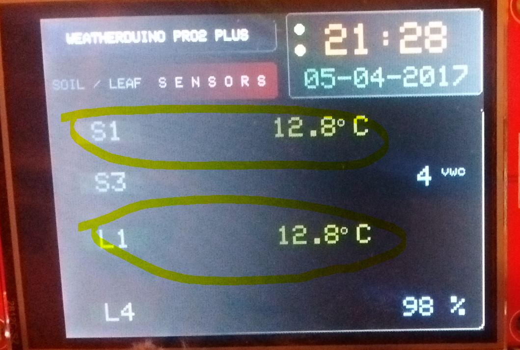
It's working on Rx dedicated screen:
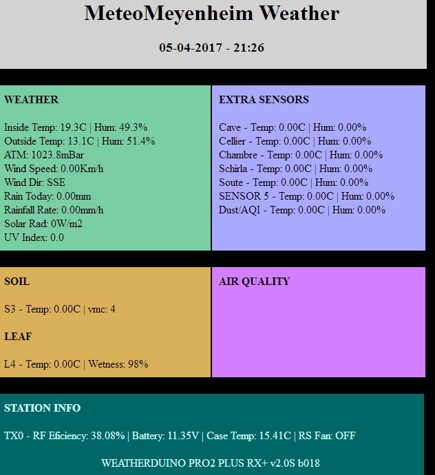
But on web server S1 and L1 temp data are missing:
My config file:
Did i miss something in the config ?
I think it should perhaps be because i only define TempSensors (Soil/Leaf) and NO SoilMoist or LeafWet sensors !
Thanks
Laurent
I'm playing with Pro2 plus RX and Tx with Soil/Leaf interface.
OneWire connected to S1 and L1.
It's working on Rx dedicated screen:
But on web server S1 and L1 temp data are missing:
My config file:
Code:
// --------------------------------------------------------------------------------------
//  WeatherDuino Pro2 PLUS - Version: 2.00 b018
//     Start of user configurable options
// --------------------------------------------------------------------------------------


// --------------------------------------------------------------------------------------
//   Define Name and ID's for this weather station
// --------------------------------------------------------------------------------------
const char WeatherStation_Name[] = "MeteoMeyenheim";

#define Station_ID            0x1B    // Station_ID, use the same value in all TX units
#define Relay_ID              0xB3    // Relay_ID,   use the same value in all WD units


// --------------------------------------------------------------------------------------
//   Define your Weather Station location
// --------------------------------------------------------------------------------------
#define LATITUDE      479    // Put here your Station latitude in tenths of degrees North
#define LONGITUDE      73    // Put here your Station longitude in tenths of degrees (minus for West)
#define ELEVATION     208    // Put here your Station height above sea level in Meters


// --------------------------------------------------------------------------------------
//   Define rules for Auto Summer Time Display, and clock adjustment
// --------------------------------------------------------------------------------------
// Example for Australia Eastern Time Zone (Sydney, Melbourne)
// TimeChangeRule aEDT = {"AEDT", First, Sun, Oct, 2, 660};    //UTC + 11 hours
// TimeChangeRule aEST = {"AEST", First, Sun, Apr, 3, 600};    //UTC + 10 hours
// Timezone myTZ(aEDT, aEST);

//TimeChangeRule PST = {"PST", Last, Sun, Mar, 1, 60};   //Portuguese Summer Time -  "UTC + 1" or GMT + 1
//TimeChangeRule GMT = {"GMT", Last, Sun, Oct, 2, 0};    //Portuguese Winter Time -  "UTC + 0" or GMT
TimeChangeRule PST = {"PST", Last, Sun, Mar, 1, 120};   // Summer Time -  "UTC + 2" or GMT + 2
TimeChangeRule GMT = {"GMT", Last, Sun, Oct, 2, 60};    // Winter Time -  "UTC + 1" or GMT + 1
Timezone myTZ(PST, GMT);


// --------------------------------------------------------------------------------------
//   Define Roll Over Hour for Meteorological Day
// --------------------------------------------------------------------------------------
#define MeteoDay_HStart 0    // Use values from 0 to 23


// --------------------------------------------------------------------------------------
//   Define your Display type
// --------------------------------------------------------------------------------------
#define DisplayType     3    // 1= LCD 20x4, 3= TFT 320x240 ILI9341

// --------------------------------------------------------------------------------------
//   Define Display Backlight TimeOut
// --------------------------------------------------------------------------------------
const byte  BackLight_Timeout =  60;   // Timeout for display backlight in minutes (1 to 255). 0 = Always ON
#define Use_ScreenSaver           1     // Instead of turn off TFT backlight show a big clock screen. 0= No, 1= Yes

// --------------------------------------------------------------------------------------
//   Define data display units
// --------------------------------------------------------------------------------------
#define Date_Time_Format 0     // 0 for dd-mm-yyyy, 1 for yyyy/mm/dd
byte Temp_Display_Unit = 0;    // 0 for ºC, 1 for ºF
byte ATM_Display_Unit  = 0;    // 0 for mBar, 1 for inHg
byte Rain_Display_Unit = 0;    // no setting, always mm
byte Wind_Display_Unit = 0;    // 0 for Km/h, 1 for mph, 2 for m/s, 3 for Knots


// --------------------------------------------------------------------------------------
//   Define the type of your Barometric Pressure Sensor
// --------------------------------------------------------------------------------------
#define Barometric_Sensor  0   // 0= BME280, 1= BMP280 2= BMP085 / BMP180


// --------------------------------------------------------------------------------------
//   Define the type of your inside Temperature / Humidity Sensor
// --------------------------------------------------------------------------------------
#define InsideTH_Sensor  0   // 0= BME280, 1= HTU21D, 2= SHT21, 3= SHT31


// --------------------------------------------------------------------------------------
//   Fine adjusts for Inside Temperature and Barometer
// --------------------------------------------------------------------------------------
const int   TemperaturaInt_offset =   0;   // Inside Temperature Fine Adjust in Tenths of Degree (-4 = -0,4ºC)
const float pressure_offset       =   0;   // Pressure Fine Adjust in mB


// --------------------------------------------------------------------------------------
//   Define the type of your outside Temperature / Humidity Sensor
// --------------------------------------------------------------------------------------
#define MainOutTH_Sensor 0   // 0 for sensor type SHT31, SHT21 or HTU21D, 1 for sensor type SHT1x or DHT22


// --------------------------------------------------------------------------------------
//   Define Wind Speed and Wind Gust resolution
// --------------------------------------------------------------------------------------
// This setting only have effect when the software is used in Davis VP emulation mode
#define VP2_WindRes     2    // If set to 2, set Cumulus Wind Speed and Wind Gust multipliers to 0.448. Wind Resolution 0.72 Km/h
                             // If set to 1, set Cumulus Wind Speed and Wind Gust multipliers to 0.224. Wind Resolution 0.36 Km/h
                             // WARNING !!! Setting this variable to 1 allows a better wind speed and gust resolution,
                             // but also limits both of them, to a maximum reading of just 91.8 Km/h
                             // If set to 0, system uses Standard Davis wind resolution (1 mph or 0.1mph with LOOP2).
                             // Weather Display users should set this option to 0 - Standard Davis wind resolution

// --------------------------------------------------------------------------------------
//   Define use of Wind Gust Spike prevention routines (mostly for FO anemometers)
// --------------------------------------------------------------------------------------
#define WindSpikeControl 1   // 0= Disable, 1= Enable


// --------------------------------------------------------------------------------------
//   Define the source of your main outside sensors
// --------------------------------------------------------------------------------------
// ---- If you are using just one TX board, the source for all items should be equal to your single TX Unit ID (most likely zero).
// ---- Define the source of your main Temperature / Humidity sensor
#define TH_OutUnit       0   // 0= Temp/Hum sensor connected to TX_Unit 0, 1= Temp/Hum sensor connected to TX_Unit 1, ...
// ---- Define the source of your Main Wind sensor
#define WIND_OutUnit     0   // 0= Wind instruments connected to TX_Unit 0, 1= for TX_Unit 1, ...
// ---- Define the source of your main Rain Gauge
#define RAIN_OutUnit     0   // 0= Rain Gauge connected to TX_Unit 0, 1= for TX_Unit 1, 3 for Auriol RF Rain Gauge
// ---- Define the source of your main Solar / UV sensores
#define SRUV_OutUnit     9   // 0= Solar Rad / UV sensors connected to TX_Unit 0, 1= for TX_Unit1, 9 for not used
// ---- Define type of Solar Radiation / UV Sensors
// ---- Support for Solar Radiation sensor type 2 and UV sensor type 4 (it is a PAR sensor not a UV Sensor) still are experimental
#define Solar_Sensor     1   // 0 not used, 1= Solar Cell "Pyranometer", 2= Apogee SP-110: Self-Powered Pyranometer
#define UV_Sensor        1   // 0 not used, 1= UVM-30A, 2= Reserved, 3= Reserved, 4= Apogee SQ-110: Photosynthetically Active Radiation Sensor
#define UV_Transmission 75   // UV Transmission percentage of UV sensor cover material

// --------------------------------------------------------------------------------------
//   Extra Sensors Settings and Mapping
// --------------------------------------------------------------------------------------
// ---- Define the source and sensor type (number) for each of the seven extra sensors, insert 9 if not used.
//      Sensors SHT31, SHT21 or HTU21D are type 0, sensors SHT1x or DHT22 are type 1
//
// ---- Source 0 means TX unit0, 1 means TX unit1...
// ---- Source 6 (Reserved)
// ---- Source 7 is for BIOS Sensor (Only Temperature is shown)
// ---- Source 8 is for Air Quality Monitor. 0= Temperature/Humidity, 1= Dust Density/AQI
// ---- (AQI sensors can be mapped to any position, but should be mapped in sequence, Temperature/Humidity always first)
//
// ---- First field = Sensor source, Second field = Sensor type (0 or 1 for TX units)
// ---- Example:
// ----                          ES0   ES1   ES2   ES3   ES4   ES5   ES6
//#define ExtraSensors_Source { {0,1},{1,1},{9,9},{6,3},{9,9},{8,0},{8,1} }
//               {0,1} - First extra sensor (ES0), will be sensor 1 from TX unit0
//               {1,1} - Second extra sensor (ES1), will be sensor 1 from TX unit1
//               {9,9} - Third extra sensor (ES2), not used - not mapped
//               {6,3} - Fourth extra sensor (ES3), will be OneWire sensor number 3 (OneWire sensors are numbered from 0 to 3)
//               {9,9} - Fifth extra sensor (ES4), not use - not mapped
//               {8,0} - Sixth extra sensor (ES5), will be Temperature / Humidity from the Air Quality Monitor
//               {8,1} - Seventh extra sensor (ES6), will be Dust Density / AQI index from the Air Quality Monitor
//
//-----                        ES0   ES1   ES2   ES3   ES4   ES5   ES6
#define ExtraSensors_Source { {5,9},{5,9},{5,9},{5,9},{5,9},{0,1},{7,0} }

// ---- Define personalized names for each Extra sensor. Attention, maximum 8 chars
#define ExtraSensor1_Name "Cave"
#define ExtraSensor2_Name "Cellier"
#define ExtraSensor3_Name "Chambre"
#define ExtraSensor4_Name "Schirla"
#define ExtraSensor5_Name "Soute"
#define ExtraSensor6_Name "SENSOR 5"
#define ExtraSensor7_Name "Dust/AQI"

#define DomoSensor1_Name "Domo1"
#define DomoSensor2_Name "Domo2"
#define DomoSensor3_Name "Domo3"
#define DomoSensor4_Name "Domo4"
#define DomoSensor5_Name "Domo5"
#define DomoSensor6_Name "Domo6"
#define DomoSensor7_Name "Domo7"

// --------------------------------------------------------------------------------------
//   BIOS soil moisture sensor settings
// --------------------------------------------------------------------------------------
// ---- Please use the included BIOS_ID_Scanner sketch to find you BIOS Device ID
#define BiosSensor_ID 0   // Device ID in HEX format, or 0 not used

// --------------------------------------------------------------------------------------
//   Soil / Leaf Interface Settings and Sensors Mapping
//   (The mapping logic is the same than used with the Extra Sensors)
// --------------------------------------------------------------------------------------
// 0 = Soil Leaf Interface not used
// 1 = Soil Leaf Interface connected to a TX unit
#define SoilLeaf_Interface  1   // 0, 1,

// ---- For Soil & Leaf data from SoilLeaf_Interface wired to a TX unit, use TX Unit number as source
// ---- For BIOS Soil Temp / Moisture use 7 as source
// ---- To disable use 9 in both fields
//                                 S1    S2    S3    S4
#define SoilTempSensors_Source  { {0,0},{9,9},{9,9},{9,9} }
#define LeafTempSensors_Source  { {0,1},{9,9},{9,9},{9,9} }
#define SoilMoistSensors_Source { {9,9},{9,9},{0,2},{9,9} }
#define LeafWetSensors_Source   { {9,9},{9,9},{9,9},{0,3} }

// ---- Define personalized names for each Soil and Leaf sensor. Attention, maximum 8 chars
#define SoilSensor1_Name "S1"
#define SoilSensor2_Name "S2"
#define SoilSensor3_Name "S3"
#define SoilSensor4_Name "S4"
#define LeafSensor1_Name "L1"
#define LeafSensor2_Name "L2"
#define LeafSensor3_Name "L3"
#define LeafSensor4_Name "L4"

// Define VWC calculation method
// Method 1 applies only for VH400 soil moisture sensor
//
// METHOD 1 - Conversion from voltage to VWC (volumetric water content) is done using the piecewise regressions provided by the manufacturer
// at http://www.vegetronix.com/Products/VH400/VH400-Piecewise-Curve.phtml
//
// METHOD 2 - Used for any sensor which have a linear output between voltage and VWC (0V=0VWC, maxV=100VWC) .

#define VWC_CalcMethod 1

// Max and Min output voltage of the analog sensors connected to Soil / Leaf Interface
// Default value for Decagon Devices LWS Leaf Wetness Sensor (3.3V power): Max. Output Voltage - 1395mV (max wetness), Min Output Voltage - 530mV (dry)

//                                                  ADC1  ADC2  ADC3  ADC4
const unsigned int AnalogSensor_MaxVoltOut[4]   = { 3000, 1395, 5000, 5000 };    // Values in miliVolts
const unsigned int AnalogSensor_MinVoltOut[4]   = {    0,  530,    0,    0 };


// --------------------------------------------------------------------------------------
//   Broadacasting settings for Wireless Display Units
// --------------------------------------------------------------------------------------
#define Relay_Data       1   // 0= Disables Data Relay, 1= Enables Data Relay


// --------------------------------------------------------------------------------------
//   Davis compatible Data Logger Settings
// --------------------------------------------------------------------------------------
#define Logger_Enable    1   // 0= Disable 1= Enable
byte ARCHIVE_PERIOD  =   5;  // Default Archive Period in Minutes (Usable values: 1, 5, 10, 15, 30)


// --------------------------------------------------------------------------------------
//   Easyweather format data Output
// --------------------------------------------------------------------------------------
#define Easyweather_Out  0   // 0= Disable (defaut) 1= Enable


// --------------------------------------------------------------------------------------
//   Internet Settings
// --------------------------------------------------------------------------------------
#define Enable_Internet     1                       // 1= Enable Internet connection, 0= Disable

//#define SSID        "----"
//#define PASSWORD    "----"


#define Enable_NTP          1                        // 1= Enable Sync time with NTP servers, 0= Disable
// NTP Server:
#define timeServer "time.nist.gov"                 // ntp1.nl.net NTP server
//#define timeServer "80.96.196.58"                  // timp.mcsi.ro
//#define timeServer "193.79.237.14"                 // ntp1.nl.net NTP server

// Weather Wunderground Settings
#define Enable_WUupload     0                        // 1= Enable upload to Wunderground,     0= Disable
#define WUupload_period     6                        // Period in minutes between uploads to WU (avoid use less than 3 minutes)
#define WUupload_InTemp     0                        // 1= Enable upload of Inside Temperature / Humidity, 0= Disable

// ---- Wunderground Personal Data
#define WUNDERGROUND_STATION_ID "----"               // Weather Underground station ID
#define WUNDERGROUND_PWD        "----"               // Weather Underground password

// Web Server Settings
#define Enable_WebServer    1                        // 1= Enable 0= Disable
#define WebServer_port     80                        // WebServer port (default 80)


#define Enable_DomoData     1


// --------------------------------------------------------------------------------------
//   Enable / Disable GPIO routines - General Purpose Input / Output ports
// --------------------------------------------------------------------------------------
#define UseGPIO  0   // 0=Disable, 1= Enable


// --------------------------------------------------------------------------------------
//   Test Mode : Never run a live system in test mode
// --------------------------------------------------------------------------------------
#define TestMode    false    // false= Normal working mode, true= Test mode only (no logger, no usb connection)


// --------------------------------------------------------------------------------------
//   Hardware settings
// --------------------------------------------------------------------------------------

// ---- Define LCD I2C address
// Only change this if your LCD don't display any data. I2C_Scanner utility may help you to find the address of your LCD display
// Default address will work most of the times!
#define LCD_I2C_Address 0x27


// --------------------------------------------------------------------------------------
//   SHT31 I2C Address - Default address will work most of the times!
// --------------------------------------------------------------------------------------
#define SHT31_address 0x44       // Default value is 0x44, but it can be changed to 0x45


// --------------------------------------------------------------------------------------
//   Presure Sensor Address (no need to change)
// --------------------------------------------------------------------------------------
//#define BMP085_ADDRESS 0x77    // I2C address of BMP085 or BMP180


// --------------------------------------------------------------------------------------
//   Debug helper
// --------------------------------------------------------------------------------------
//#define PRINT_DEBUG_NTP_UPDATE    // Prints to serial monitor messages related to sync time with NTP server
//#define PRINT_DEBUG_WU_UPLOAD     // Prints to serial monitor messages related to Weather Underground upload.
//#define PRINT_DEBUG_TCP_SERVER
//#define PRINT_DEBUG_AURIOL
//#define PRINT_DEBUG_BIOS

// ---------------------------------------------------------------------------------------------------
//     End of user configurable options
// ---------------------------------------------------------------------------------------------------I think it should perhaps be because i only define TempSensors (Soil/Leaf) and NO SoilMoist or LeafWet sensors !
Code:
#define SoilTempSensors_Source  { {0,0},{9,9},{9,9},{9,9} }
#define LeafTempSensors_Source  { {0,1},{9,9},{9,9},{9,9} }
#define SoilMoistSensors_Source { {9,9},{9,9},{0,2},{9,9} }
#define LeafWetSensors_Source   { {9,9},{9,9},{9,9},{0,3} }
Thanks
Laurent