


29-05-2017, 09:50
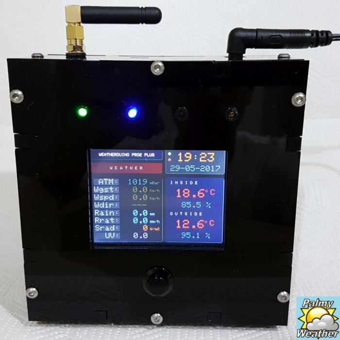
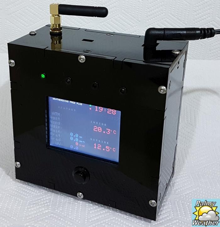
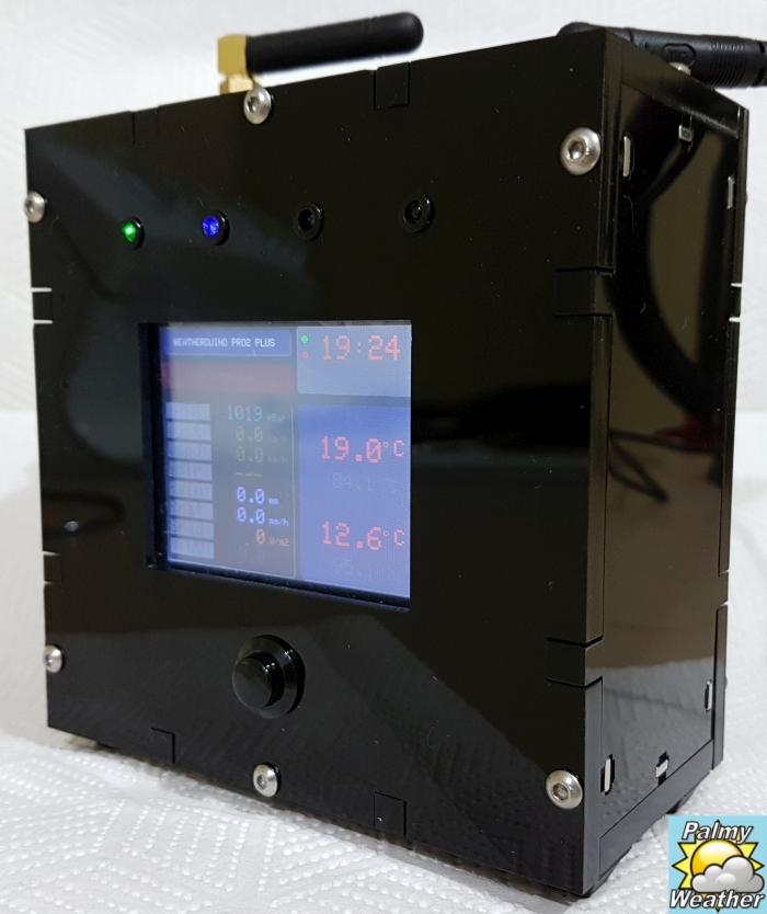
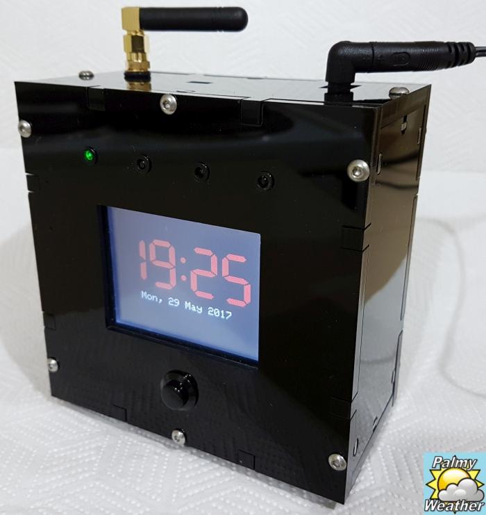
I am pleased to tonight show off my completed "WeatherDuino Pro2+" receiver unit. It has been a long time coming, but I have finally got around to getting a custom box designed and created to house the receiver.
Although this receiver was a little more expensive to purchase, it is so easy to assemble and you will have it up and running in no time. The extra parts that need to purchase are very easy to find on the internet as long as you do not mind the time it may take for them to be shipped.
The hardest thing I found was finding an enclosure I was happy with to house the circuit board. This is why I ultimately went off to a local plastics guy and got a design made exactly how I wanted it. This enclosure is 105mm wide x 105mm high x 50mm deep, giving plenty of space to work inside and wire things up.
You will see 4 LED's across the top. The first one (green) is a power light, useful to know the device is still on when the LCD screen may be turned off. Second in from the left is a blue LED which indicates data is being received from the transmitter. The third LED is a red one which will flash when data is being sent to the PC and other receivers in the home. Finally the last LED is connected to the GPO circuit and will come on when a set condition is met. I may look at customising the GPO to include a buzzer on the second relay control.
Hopefully this will give others some ideas on what can be created for their projects.
Happy Building!
PalmyWeather
Although this receiver was a little more expensive to purchase, it is so easy to assemble and you will have it up and running in no time. The extra parts that need to purchase are very easy to find on the internet as long as you do not mind the time it may take for them to be shipped.
The hardest thing I found was finding an enclosure I was happy with to house the circuit board. This is why I ultimately went off to a local plastics guy and got a design made exactly how I wanted it. This enclosure is 105mm wide x 105mm high x 50mm deep, giving plenty of space to work inside and wire things up.
You will see 4 LED's across the top. The first one (green) is a power light, useful to know the device is still on when the LCD screen may be turned off. Second in from the left is a blue LED which indicates data is being received from the transmitter. The third LED is a red one which will flash when data is being sent to the PC and other receivers in the home. Finally the last LED is connected to the GPO circuit and will come on when a set condition is met. I may look at customising the GPO to include a buzzer on the second relay control.
Hopefully this will give others some ideas on what can be created for their projects.
Happy Building!
PalmyWeather